
Finite Element Analysis (FEA) provides solutions for structural and functional performance challenges
Dale Berry, Director of Technical Marketing, SIMULIA
Mahesh Kailasam, Industry Lead for Energy, SIMULIA
Jack Cofer, Director, Turbomachinery & Power Generation, Engineous Software, Inc.
Power generating equipment and structures span an extremely wide range of engineering domains; gas and steam turbine blades, nuclear plant piping, wind turbine pylons, wave energy converters—all need to be designed for both immediate cost-efficiency and for long-term productive lifespans. The power engineer needs a robust, flexible design toolkit for coping with the ongoing evolution of industrial technology, materials, energy sources and environmental regulations. Realistic simulation with finite element analysis (FEA) is a critical tool that provides solutions to a vast scope of engineering challenges.
What’s the ideal configuration of a turbine blade? Which new alloys will work best in a gas/steam combined cycle plant? How can spent nuclear fuel be stored in a safe and secure manner? How can you adapt a land-based wind turbine design to a deep-water installation? Can electricity be generated from wave power cost-effectively? FEA can help guide the design process and provide answers to these and other important physical-performance questions. Recent developments in computer hardware, numerical solutions, and design optimization software are providing results faster and cheaper.
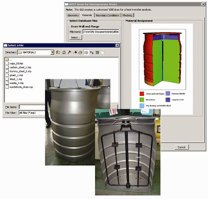
Image 1. Material Property dialog box of Abaqus/CAE customization for standardized waste package safety assessments. File selection dialog box allows the selection of material properties from a database. The image shows 270 Degree sweep of Abaqus axisymmetric model showing the drum (waste container) components and contents. Inset Photograph shows a 500 liter drum sectioned to expose its internal components. Courtesy of AMEC Nuclear UK Ltd.
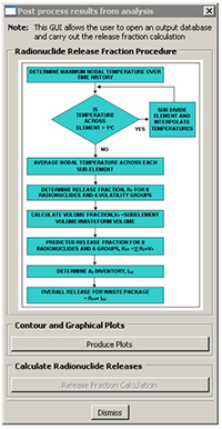
Image 2. Post processing dialog box of Abaqus/CAE customization for waste package safety assessments. Allows the user to initiate the calculation of radionuclide releases from the waste package – activates python script which interrogates the Abaqus simulation results (.odb) file. Diagram in dialog box shows the decisions being made during the radionuclide release calculation. Courtesy of AMEC Nuclear UK Ltd.
FEA helps evaluate realistic performance during the design phase
FEA is a widely accepted computer simulation methodology for modeling, evaluating, and optimizing a product’s mechanical and structural design. The technology has a long history of effective use within the energy industry as well as in the Aerospace and Automotive sectors. Engineers generally start with a CAD model – perhaps of an airfoil, a nuclear plant piping component, or the blade of a wind turbine – and then use FEA software to transform that model into a 3D mesh of geometric units, which are the ‘elements’ in finite element analysis. Each element is assigned a distinct size and shape mathematically representing a finite section of the model. Linked together by nodes that quantify their interrelationship, the elements (which can number in the hundreds of thousands or even millions) are further constrained by boundary conditions, material characteristics, and a host of other inputs dictated by what type of product or structure is being modeled.
Once an FEA model is set up, any number of static, dynamic, linear or nonlinear events, including contact, collisions, buckling and/or collapse scenarios, and even multiphysics analyses (thermal-structural, fluid structure interaction and/or computational fluid dynamics), can be analyzed. Feedback from the FEA solution (‘virtual testing’) is then used to evaluate and modify the CAD design, repeatedly if necessary, until the desired product functionality and durability are reached.
The results of FEA are typically verified with real-world tests. However, when used in the correct process, and leveraging historical engineering test data, FEA is capable of reducing design time as well as the expense of extensive physical prototyping. The technology has been accelerated in recent years with the addition to the engineer’s toolbox of process integration and design optimization software, as well as multi-core, high-performance computing.
The diverse engineering needs of power generation have benefited greatly from advancements in FEA because the software can be focused very acutely on almost any design problem. As simulation providers have worked closely with their customers over the past three decades to meet the specific demands of their industries and/or products, cross-fertilization between industries has further broadened software capabilities.
In the case of Dassault Systèmes’Abaqus unified FEA software from SIMULIA, technology developed to simulate aircraft engines translates into strong support for gas and steam turbine design. Technology developed for analyzing gaskets in automotive engines can also be used to analyze piping connections. Structural design and soil interaction capabilities, proven through analysis of oil & gas platforms, are now being applied to the development of offshore wind structures. Geophysics capabilities can help address seismic issues in the structural design of nuclear plants while realistic simulation of repetitive contact helps strengthen wave energy converter designs to withstand years in the roughest seas. And the composite materials used in ever-increasing numbers of products can be modeled with new simulation technology developed for use in aerospace structures.
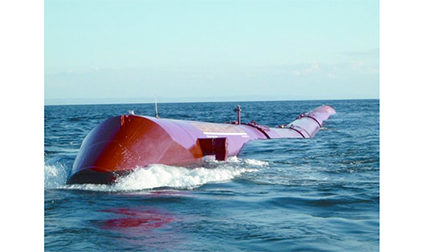
Image 3. Pelamis Wave Energy Converter during sea trials.
Meeting the design needs of power generating turbomachinery
The turbomachinery industry faces a host of obstacles to profitability, including tighter environmental regulations, pressure to reduce design cycle times and costs, and constant demand to develop innovative, high-performance products. In this highly competitive environment, performance is everything. Weight matters, fuel and/or electricity efficiencies matter, emissions matter. Prototypes are large and expensive: while molding and casting an engine mount can be accomplished in a week, it can take nine months to build a prototype to verify and validate that engine’s real performance. Because new engine designs require years of development, the technology that a turbine manufacturer employs truly needs to be state-of-the-art. The ability to predict the performance of an innovative turbine design with FEA is extremely useful.
Almost every component of a gas, steam or gas-and-steam power plant can be analyzed with FEA. All turbomachines work on essentially the same set of physics but they can have very different design environments. One of the most common FEA applications is turbine blade design, particularly of the last stage blades that are long and thin and carry a huge mechanical load. The strength of materials from which the blades are manufactured is critical: the high-temperatures and low pressures at which a gas turbine functions—or, by contrast, the lower temperatures and widely fluctuating pressures along a single steam turbine rotor— will affect the behavior of parts and materials in different ways all along the 30 or 40 stages in a power plant. Extensive FEA materials libraries help the design engineer model and predict the response of different materials—be they titanium, advanced alloys, ceramics or composites—under such huge temperature and/or pressure differentials.
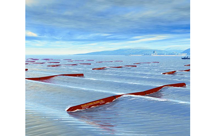
Image 4. A 30 Megawatt ‘wave farm’ of Pelamis Wave Energy Converters will occupy a square kilometer of ocean surface and produce electricity for 20,000 homes. Courtesy of Pelamis Wave Power.
Blade tuning to avoid flutter is another design issue where FEA, often in combination with a computational fluid dynamics (CFD) code, can be extremely powerful. The analysis of the interaction between vortex shedding from the blade and its mechanical vibration is a very nonlinear, transient engineering problem: if the vortex shedding excites a mode in the blade it can shatter catastrophically. Modal analysis with FEA can spot the problem in advance.
Other important FEA applications in turbomachinery include examining the attachment of blades to the disk and predicting the performance of the casings that contain the blading. Competing tradeoffs between weight, performance and size must be balanced by the designer; using FEA can help avoid over-design as well as under-design. The comprehensive procedure library in an FEA code enables the engineer to evaluate dynamics, cyclic symmetry, creep, contact, natural frequency extraction of a spinning engine and more.
Optimization technology plus FEA equals a powerful combination
Design optimization software, used in combination with FEA, enables engineers to automate the exploration of multiple design alternatives and arrive at design performance answers faster and with higher degree of confidence than with manual analysis techniques alone. Many turbomachinery design engineers are using a product called Isight, originally developed by Engineous Software, for process integration and design optimization. Following the acquisition of Engineous by Dassault Systèmes earlier this year, SIMULIA recently released Isight for Abaqus, which delivers the benefits of design optimization connected with robust FEA technology.
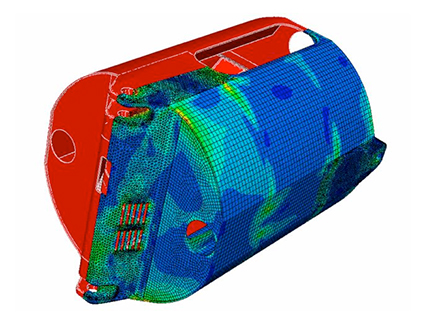
Image 5. Abaqus finite element analysis is used by Pelamis Wave Power engineers to evaluate the structural integrity and nonlinear behavior of their power generating machines.
The combination of optimization with an FEA solution is a very powerful design tool in turbomachinery because every plant has a unique layout and turbine configuration that require exacting customization of the equipment. In the blade-tuning example above, an Isight blade shape generator can be connected with an FEA code to automatically, quickly, create and evaluate multiple configurations for a blade until the optimum shape is found that avoids resonance with the frequencies in the machine. The process can be easily duplicated throughout every stage in a steam turbine rotor. Optimization is also readily applicable to the forging process for turbine wheels.
Optimization can also be applied on a wider scale, for example, to the miles of pipes found in power plants. In Japan, stringent earthquake regulations dictate the use of many expensive hangers that secure pipes to the structure of the plant. Using an FEA model of the piping system, in conjunction with an optimization program for determining the number and location of the hangers, plant design engineers are able to meet safety requirements with the minimum number of hangers, avoid over-designing, and save millions of dollars in every installation.
Energy cost is also a significant driver in turbine design. While efficiency and reliability are certainly important, the overall goal of a turbine manufacturer is to minimize the cost of electricity for the power plant owner. The latest optimization tools enable analysis of not only the baseline efficiency of a machine but also the degradation in performance between service outages, and the cost of servicing a machine to restore performance, over the entire 20- to 30-year life of the machine.
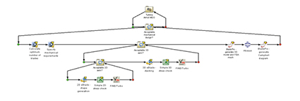
Image 6. The complex turbine blade design process can be captured in an Isight-FD workflow to perform automated aero/mechanical multidisciplinary design optimization (MDO) using Abaqus with a parametric 3D blade shape generation tool, a CFD code, and a specialized blade modeling and meshing code.
Keeping track of all the FEA iterations, design processes simulations and optimization results in a turbomachinery plant is critical to cost-efficient management of such complex, yet essential tools. New solutions for managing simulation data, processes, and applications are now becoming available to capture simulation workflows, keep projects on track in real-time, avoid duplication of design analysis efforts, and secure intellectual property associated with proprietary designs.
Nuclear power industry has a long history of FEA use
FEA has been employed by the nuclear industry for decades because it provides sophisticated calculation techniques compatible with the demanding quality standards required for nuclear power plant construction. SIMULIA in particular has developed many of its cross-industry Abaqus capabilities from work originating in this field.
In the area of nuclear plant equipment, e.g. reactors, piping and concrete protection barriers, FEA provides a variety of tools, such as material models for plasticity, creep, and the behavior of concrete; fracture and failure analysis techniques; and special pipe (elbow) elements for simulating all operating aspects of the plant. For example, piping in nuclear plants can be simulated (pipe elbows are a specific type of finite element) and evaluated for heat transfer, thermal stress and pipe-whip. Pipe hanger FEA optimization can be carried out in similar fashion to the power plant example noted above.
In the all-critical arena of nuclear fuel storage, nonlinear FEA can be used for drop testing of spent fuel storage vessels, to perform thermal-stress analysis of the storage mechanism, or to evaluate the effects of fire on a storage vessel for radioactive waste material. Other applications include thermo-hydro mechanical safety evaluations of underground storage, taking into account soil saturation and compaction over long periods of time. This latter example employs similar capabilities—such as soil models and coupled pore fluid diffusion and stress analysis—as those used in geomechanics and the oil & gas industry.
The nuclear industry is facing two major challenges going forward: the development and installation of next-generation nuclear reactor technologies, which will certainly benefit from extensive analysis with FEA, and service assessments of existing older plants for which FEA can be used either for recertification or for safe decommissioning.
The use of simulation lifecycle management (SLM) solutions, while an important tool across the power industry, is of particular significance to the nuclear field. Keeping records of design modifications and updates in conjunction with plant function and operations data over long periods of time is clearly critical.
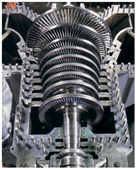
Image 7. Steam turbine casing, rotor, and blading
Wind Power: FEA leverages expertise in offshore exploration and aerospace
The wind power industry is experiencing something of a boom lately as government and private sector support continues to grow in this newer energy field. Taller structures are being designed to take advantage of stronger wind speeds at higher elevations and also to offset greater installation costs in the case of offshore wind farms.
The design and simulation of wind turbine towers and foundations is second nature for FEA software vendors with extensive experience in the oil and gas offshore industry. All of the necessary material models are available for simulating foundations, such as concrete, the behavior of soils, and soil/structural interactions. Linear dynamics capture vibration (earthquake) effects, while static and dynamic nonlinear analyses simulate complex fluid-structure interactions or failure mechanisms.
Rotor blades are possibly the most visible and critical part of a wind turbine. Composites are a leading blade material; FEA modeling techniques for composites, initially driven by aerospace, are highly applicable when exploring such new materials for strength and durability in challenging weather. The software supports composite pre-processing steps such as definition of layups, distribution of orientations and thickness, and visualization of various plies. For modeling purposes, a wide range of element types (solid shells, continuum shells, and so forth) can be used together with different material and failure models, such as the Virtual Crack Closure Technique (VCCT), which was developed by Boeing and refined by SIMULIA, or cohesive elements.
A less visible, but still critical, part of a wind turbine is the bearings; several bearings manufacturers use Abaqus FEA to model and simulate the contact behavior of parts in a bearing quickly and accurately. The software solution takes advantage of built-in stabilization features and advanced contact algorithms. Process automation and optimization tools can be applied to FEA analysis of bearings and other aspects of wind power development to identify optimum design parameters for the most efficient and cost-effective design.
Power from many sources
One of the more novel power generation applications in which FEA has been implemented in recent years is Pelamis Wave Power’s wave energy converter, which floats on the ocean surface and generates electricity from waves. Hydraulic rams resist the motion of the waves and pump hydraulic fluid through electricity-producing generators; a wave farm of multiple units can provide electric power for thousands of homes. Pelamis is studying fatigue and durability in their product using FEA applications to analyze the performance of both small components and larger assembly simulations and make appropriate design modifications.
Other alternative energy sources, including solar power and fuel cells, are becoming viable on a scale that increasingly makes economic as well as environmental sense. The cost-effective development of both traditional and newer energy sources requires state-of-the art simulation solutions, such as nonlinear FEA, design optimization, and simulation lifecycle management. Using these technology tools enables engineers to evaluate real-world behavior of a diverse array of power generating equipment and make rapid, and accurate, performance-based design decisions to help meet energy needs today and in the future.
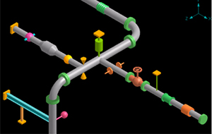
Image 8. The number and locations of hangers in a complex power plant piping system can be optimized to meet stringent earthquake requirements while minimizing cost by using Isight with specialized piping modeling and FEA codes.