
By Kamil Szepanski, Volume Graphics
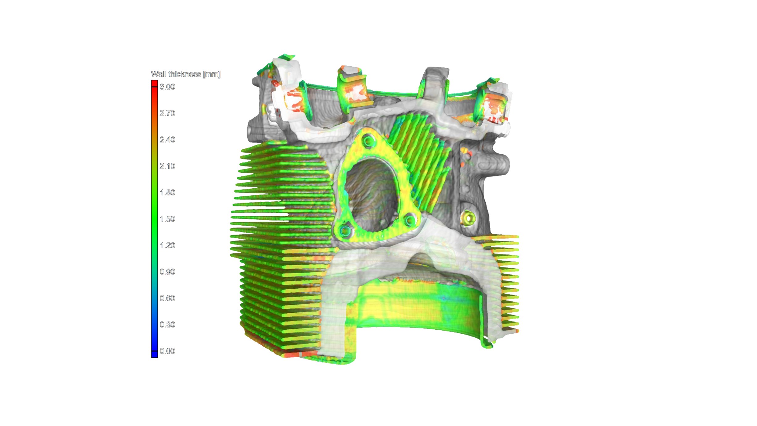
Image 1. A wall thickness module in CT analysis software automatically localizes and color codes areas with an insufficient or excessive thickness or gap width directly within a voxel, point cloud, mesh or CAD data set. In this example, the module was used to examine the wall thickness of a Lycoming IO-540-E1B5 aircraft engine. Scan courtesy of YXLON US; image courtesy of Volume Graphics.
Quality assurance and flight certification of critical aerospace parts and assemblies have reached new levels of sophistication in recent years. Leading aerospace and defense manufacturers worldwide now consider computed tomography (CT) scanning to be an essential part of their non-destructive testing (NDT) toolkit. Far more powerful than the CT used to scan the human body, industrial CT can penetrate almost every material, from superalloys to lead, revealing hidden details that previously could only be found by cutting and destroying finished parts.
However, because scanning is always performed after manufacturing, CT-image inspection alone without further analysis can lead to over- or under-estimation of the significance of visible anomalies. This can lead to high rejection rates, time-consuming corrective measures, or the addition of excess weight added to designs in compensation—all negatives in expensive aerospace projects.
The solution, more widely used in Europe but now increasingly being adopted in the U.S., is advanced software that uses CT-scan data to recreate a three-dimensional volume of a part containing complete, detailed information about its geometry, both surface and interior. This in turn can be compared against the part’s master model and analyzed for a wide variety of performance and durability metrics that, recorded and categorized, can be used to support qualification and flight certification.
A look back at the development of industrial CT analysis
Not surprisingly, physics-department engineers at Boeing were among the early enthusiasts for the use of CT to assess aerospace-part quality, writing a chapter for the Review of Progress in Quantitative Nondestructive Evaluation in 1991 about “a new inspection capability for aircraft hardware.”
“We believe that the most beneficial application of CT will be in using CT data for component acceptance by engineering criteria rather than inspection standards,” noted the authors.
At that time, the more sophisticated analysis tools that would be needed to take full advantage of scan data were in the early stages of development. The authors described CT scanning of an aircraft drum casting that revealed a defect in the outside wall. To predict the potential impact such a defect might have on the component’s performance, the scan data was converted to a 2D digital model of the part and then transferred to a finite element analysis (FEA) code. FEA was a nascent tool at the time, not yet widely used; while the effect on performance was predicted quite accurately, the analysis itself involved expert setup and long run times and the images were low in resolution.
By 1997, German physicists at Volume Graphics had developed the first software able to directly process CT slice-image stacks on standard PC hardware. A year later, the application did away with the need to analyze data slice-by-slice, covering volume in all three dimensions.
Understanding both the geometry and the physics of a part
Today’s advanced industrial CT machines produce extremely high-resolution (generally between 1 and 400 microns), data-rich images. Advanced CT-scan analysis software transforms this data directly from the CT file to a digital 3D image (i.e. as three-dimensional voxels, rather than 2D pixels). The software has various functionalities that highlight internal and external geometries, detect voids and inclusions, confirm densities, and perform high-accuracy metrology for first-article dimensional inspection (such as for AS9102). Measurement templates present data, such as the geometry of every individual void detected in a part, in formats that can be included in the product manufacturing information (PMI) database for the product.
Also integrated within the software is finite element analysis (FEA) functionality (much more sophisticated than in the 90s and empowered by high-performance computing, automated “meshless” solver algorithms and sophisticated multiphysics capabilities). This capability predicts part stability, strength, and performance with accuracy, speed and ease-of-use that have become transformative for those aerospace manufacturers who’ve adopted it.
An integrated CT-data-analysis software package reproduces the exact geometry and behavior of an individual part or component (from a single bracket to a full engine block) no matter how it was made—or what it’s made of. Whether it’s a casting, a composite layup, or additively manufactured (AM) using aluminum, titanium, Inconel, carbon fiber or ceramic composites, CT scanning power can be adjusted to penetrate almost every material, and the analysis software be put to work on the resulting data.
In every case, deviation from the part’s master CAD model, as well as failure potential under a wide range of multiphysics conditions such as stress, vibration, heat, electromagnetics, etc., can be automatically identified. This helps manufacturers evaluate whether defects are above or below tolerance criteria, and supports critical go/no-go decisions that can have significant economic impact. What’s more, quick feedback on as-manufactured parts can inform design decisions, guide adjustments to mold dimensions, and help direct changes to manufacturing equipment settings that will optimize the final product.
Here’s a look at the use of industrial CT-analysis software in a selection of key aerospace and defense manufacturing applications.
Additive Manufacturing
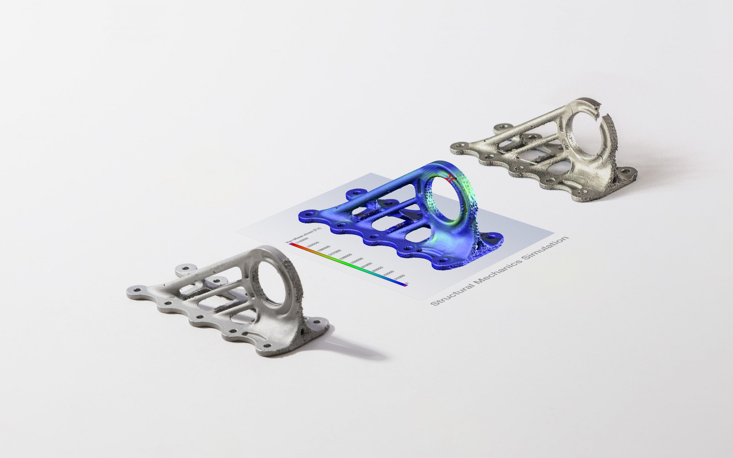
Image 2. (Left) An additively manufactured aircraft cabin bracket (miniaturized, without surface finishing, and with the typical appearance of a 3D-printed part) with deliberately inserted discontinuities. (Middle) Volume Graphics software generates a color-coded display (finite element analysis) of the locations of the weak points directly on the scan of the real component. (Right) Part after destructive test shows component failure in the exact spot predicted by the software. Part courtesy of Airbus Emerging Technologies & Concepts; software images courtesy of Volume Graphics; part manufactured by Concept Laser.
AM is proving its worth in safety-critical aerospace components. With production parts in the air (GE took an early AM lead with their Leap engine and, more recently, the Catalyst engine for their advanced turboprop), this technology has become an important option for lightweighting structural as well as non-structural air and spacecraft components.
Airbus is using AM widely; the 3D-printed titanium cabin brackets used throughout the A380 weigh 30 percent less than the traditionally milled pieces used in previous aircraft. The structural mechanics simulation module in the Volume Graphics software the company employed was verified on this same part (see Image 2). As lighter, yet more costly, superalloys are increasingly being employed for weight reduction in aerospace, CT-based evaluation of the performance of these materials is becoming a valuable part of the aircraft manufacturer’s toolkit.
The complex internal details made possible through AM, such as lattice structures and cooling channels, can only be fully evaluated through CT-data analysis. The software works directly on the voxel data of the scan, overlapping the part and its CAD master model for direct comparison. When there are deviations between these, automatic manufacturing-geometry correction calculates suggested changes to the geometries of 3D-printed parts.
There can be unpredictable side effects from laser sparks and floating powder occurring inside a 3D-printing machine, particularly during metal-AM builds of aerospace components. CT-scan analysis software provides visual confirmation of porosity, voids, inclusions, blocked cooling channels (very important to control in AM-produced turbine blades), surface dimensional and thickness variations, and warping. Virtual (simulation-based) stress testing assesses the impact of such discontinuities on part stability—including directed force, torque and pressure analysis of static loads—and calculates the Von Mises stresses to identify the most likely locations of failure.
Composites
The newer, larger aircraft of today contain a significant proportion of composite materials, which provide stiffness and structural strength exceeding that of traditional metals and deliver the value of weight savings and decreased fuel consumption. There are a number of issues that arise in composite manufacturing that can be addressed in greater depth through CT-scan data analysis.
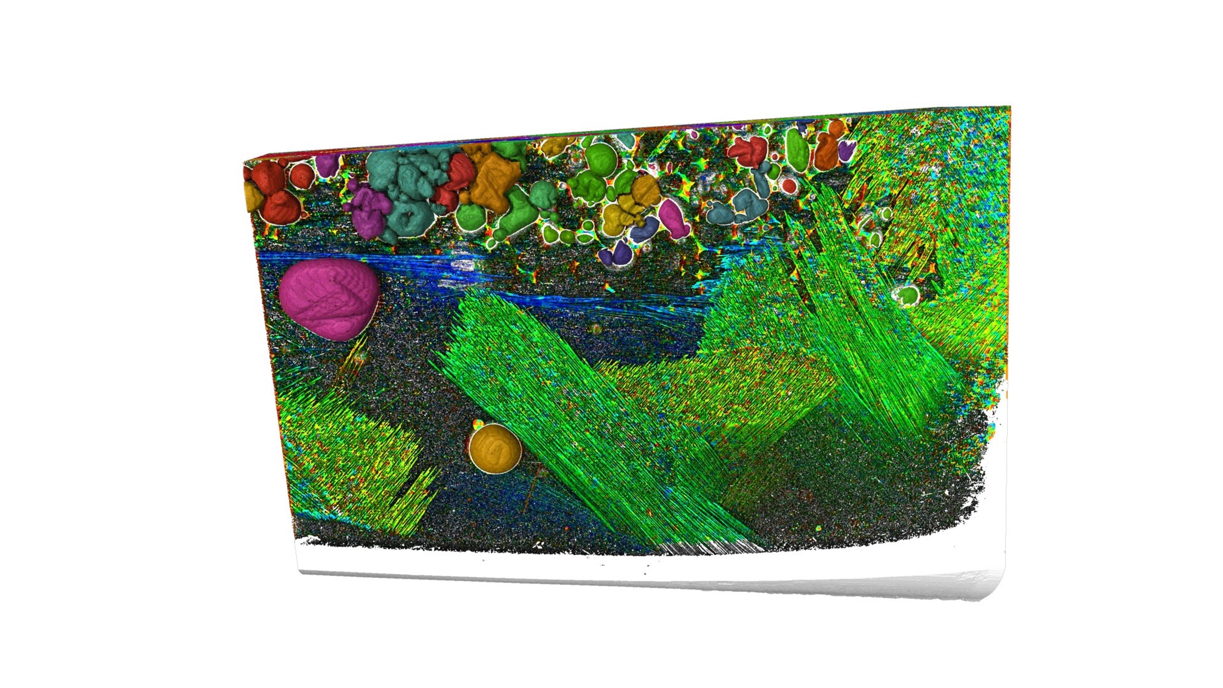
Image 3. CT analysis software clearly shows the fiber orientation within a helicopter rotor blade made of lightweight, fiber-reinforced plastic composites (GRP). Scanning courtesy of TPW Prüfzentrum, image courtesy of Volume Graphics.
- Proper orientation of fibers is critical to robust performance of composite wings, blades, fuselages and bulkheads. Fiber-composite material analysis software provides insights into CFRP and GRP, visualizing both local and global fiber orientations (Image 3), and aiding comparison of nominal and actual values of individual components of the orientation tensor; these values can be fed into simulation software to assess stress and durability.
- Part delamination is a major flaw that can be challenging to evaluate fully in composite components made up of multiple layers; visualization of CT scans makes delaminations visible so their causes can be addressed.
- Undulations arising from process errors—such as inadequate material, errors in layering technique, excess application of resin—can be uncovered quickly and remedial steps taken to correct manufacturing methodology flaws.
- Gluing of components is of particular importance with composites. Analysis software helps visualize how well glue was dispersed, how big the contact zone is between glue and material, and whether any breaks have occurred.
Welds
The art of welding in aerospace is as old as the first commercial aircraft. The integrity of welds is obviously of critical importance; last year the International Space Station detected a loss of oxygen that was a direct result of a weld-pore issue.
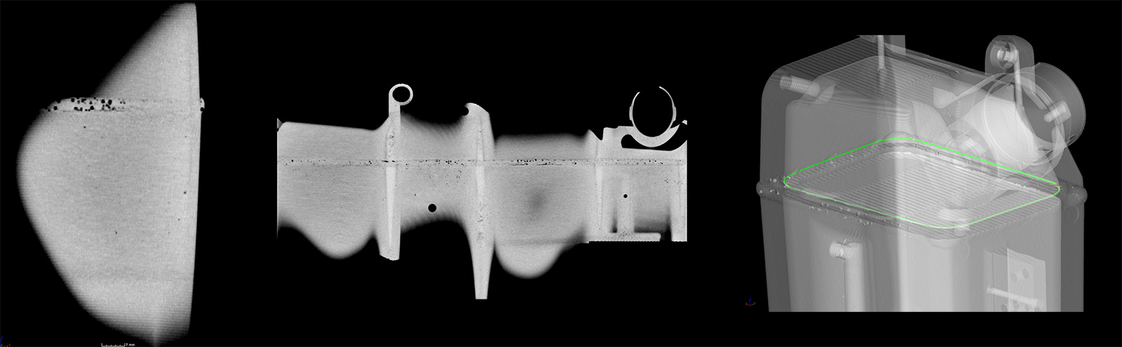
Image 4. (Left) Regular orthogonal CT slice of a weld seam; only a small portion of the existing pores are visible. (Middle) Analysis software provides an “unrolled” view of the same weld seam; pores and cracks are clearly visible along the entire weld seam. (Right) 3D rendering of the tank showing the path (green) used to unroll the weld seam. Images courtesy of Volume Graphics.
A variety of processes have been developed to join both traditional and newer metals such as titanium, aluminum, and magnesium. Weld seams of all types have restrictions on thickness and can contain porosities and cracks for which CT analysis software can be an extremely valuable identification tool. Scanning a typical S-shaped weld for defects using CT alone requires inspecting individual image slices one at a time. Viewed this way, the full effect of a crack or porosity can remain undetected. Using analysis software, however, the S-shape of the weld can be defined as a straight path that more clearly visualizes the full extent of the discontinuity (Image 4).
A methodology with broad applications in aerospace
These are just some of the many ways that CT-scanning plus software analysis are increasingly being employed by the aerospace industry (including commercial, defense and NASA) to ensure product integrity and meet certification requirements. Other applications of the methodology include engine wall-thickness evaluation (Image 1), injection-molding part geometry correction, soldering inspection of circuit boards, evaluation of hot-formed aircraft parts, reverse engineering of older aircraft, crash forensics and more.
A growing trend in aerospace manufacturing is at-line, or even in-line, use of CT scanning plus analysis software implementation right on the production floor. Accurate and complete understanding of how changes in manufacturing parameters can affect the final product is essential when the goal is the level of quality that flight-critical products require.