
By Johannes Mann, Global Business Development Manager for Volume Graphics
CT data analysis and visualization software is used widely in the automotive industry for evaluating molded-fiber plastics, cast, composite, foam, machined and additive parts, along with processes such as hot and cold joining technologies. Fabricating and metalworking businesses, serving automotive and other industries, encounter these diverse materials and processes as both primary suppliers and as post-processors.
The powerful capabilities of CT data analysis not only serve a quality mission in R&D and in-line inspections—for everything from cylinder heads to plastic connectors to turbine blades—but are also now supporting upfront design creation and improvement. This expanding role emphasizes the enormous possibilities of the all-digital movement in manufacturing and the trend toward focused automation, both in software and in shop tools.
The digital transformation and CT
Driven by competition, the all-digital transformation is quickly gaining momentum within automotive development centers and among suppliers. Because physical, costly and time-consuming iterations are the enemy of profit and competitive advantage, development is being virtualized as far as possible.
Shops already understand the impact of closed-loop inspection of surfaces from CAD to CNC to Coordinate Measuring Machines (CMM). But CT analysis is now taking both surface and interior inspection much further. Automated design-geometry adjustment and repair programs exist to correct and/or offset issues that stem from the manufacturing process itself. The software can detect and visualize material distortions and design defects, then compare values against nominal limits to ensure final part quality. This is essentially an as-designed, as-manufactured comparison that leads to an accurate model corrected for tolerances and dimensions. An added benefit is that the real-world part information acquired by CT scanning can be fed into simulation software to further enhance predictions.
Increasingly, whole teams along the product life cycle are moving closer together and getting involved in development. CT analysis software is being used to perform metrology on simulation results (virtual production parts) to check if a given design can be developed into a robust part. Fabricating and metalworking shops have long played a role in Design for Manufacturing (DFM) analysis of incoming designs. This role will expand as teams collaborate with their Tier 1, 2 and 3 suppliers to bridge design and manufacturing domains—now narrowed and made more accessible by digital advances.
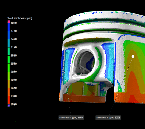
Image 1. VGSTUDIO MAX CT analysis software from Volume Graphics shows the wall thickness color-coded directly on the surface of a piston, helping engineers understand design intent and final manufacturing outcomes.
What lies ahead for automotive inspection and design?
No matter what process is used for production of automotive parts—casting, molding, additive manufacturing or machining—CT data analysis can be relied on for defect detection, behavior prediction and design correction. Recent software improvements add even more detail and automation to non-destructive CT inspection, which makes material and part performance evaluations easier and, overall, more cost efficient relating to customer satisfaction, direct costs, and future warranty and service issues.
Two basic capabilities highlight the advances available for all processes, yet truly show their value for traditional casting and mold tooling, along with the emerging process of AM for production parts. Software for manufacturing geometry correction and mesh compensation standout as all-purpose applications for improving parts.
Manufacturing geometry correction
Manufacturing geometry correction is a function that equally serves the injection molding and casting industries. Scanned data is imported into an analysis program and compared to the master CAD geometry as an overlay. This highlights the nominal range of accepted tolerances, feature and surface dimensions, deviations, warpage, porosity, and metallurgical defects. Graphical color plots allow digital comparisons and call-outs to be easily recognized. Designers, manufacturing engineers and quality specialists can then determine corrective actions in the cast set-up or mold.
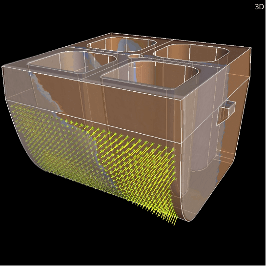
Image 2: The Manufacturing Geometry Correction Module offers functions to optimize tools or 3D printing geometries. Based on scans of actual parts it calculates suggestions for necessary changes to tools and molds to minimize iterations. Shown is the result of a manufacturing geometry correction as a visualization of compensated fit points ready for export. Analyzed with Volume Graphics software, version 3.5.
For toolmakers, this process conclusively determines whether the design or mold manufacture is out of sync. Normally, such situations are cause for indecision, more iterations and even reliance on “black art” approaches. Casters, in turn, face similar challenges and faults. The potentially geometrically complex parts and the push to hit process limits means that only CT analysis can address early test and full-production quality control.
Mesh compensation
Mesh Compensation is important to those working in process simulation and AM/3D printing. This inspection and design-repair offering provides a look at the relationships between mesh elements. From these insights, engineers can better interpret part warpage, deformations and displacements with the goal of having designs automatically compensated to match their manufacturing intent. The compensations work well even for lattice structures and other complex geometries. Such software can shorten the 3D-printing process by systematically running two sequential design-compensation routines to ensure that a first print meets nominal values.
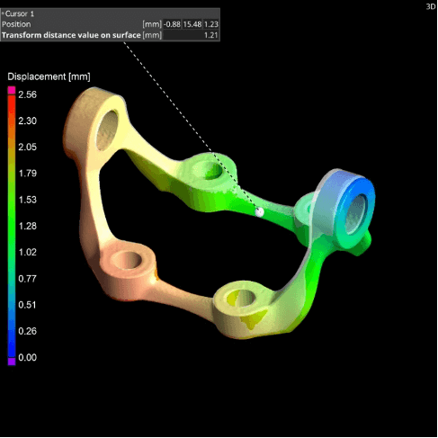
Image 3 (a). Enhanced Mesh Compensation (a). A new compensation mesh color overlay in Volume Graphics’ industrial CT Version, VGSTUDIO MAX 3.5, helps users to clearly visualize, analyze and annotate any displacements in the compensation mesh.
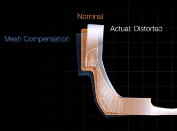
Image 3 (b). Enhanced Mesh compensation (b). The software offers a sophisticated function that eliminates deviations in the actual geometry caused by distortions such as warpage.
Porosity detection and evaluation for castings
Other new software capabilities offer porosity compliance checks that satisfy Reference Sheet P 203 of the German Foundry Industry (BDG) next to the well-known P201 & P202. Engineers can use this approach to inspect the whole casting, sub-areas, or post-machining issues in the finished part.
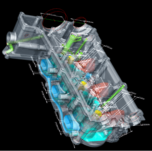
Image 4. Shown is a cast section of an automotive cylinder head with dimensions scanned, captured and checked against the 3D digital master. From Volume Graphics VGSTUDIO MAX 3.5 Cast & Mold package.
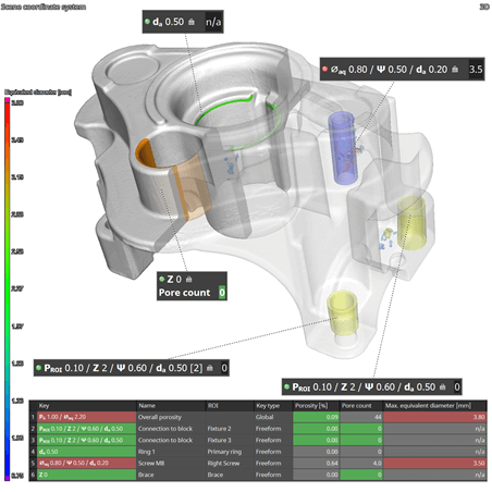
Image 5. A porosity analysis of a mounting bracket for an automotive high-pressure pump. The new P203 analysis within Volume Graphics’ Extended Porosity/Inclusion Analysis Module for VGSTUDIO MAX allows teams to evaluate part porosity using an intuitive interface. The analysis includes porosity tolerance per region, equivalent defect diameter, and total number of defects as tolerancing parameters. Often, it is not possible to avoid casting defects altogether, but they can be controlled to prevent them from occurring in locations critical to a part’s functionality.
The growing role of CT in industry
CT-analysis software is more powerful, automated and easier to use than ever before. It is now a key design tool as well as a post-production inspection and validation method. It can serve every automotive department from R&D, design, performance (FEA/NVH/CFD) and process simulation, to manufacturing and quality control. It serves nearly every material and process, and is appropriate for in-line, series production and batch inspection. While more costly upfront than other approaches, the total-cost savings and value-added role of CT in emerging all-digital smart factories presents clear benefits for fabrication and metalworking organizations.