
By Annalise Suzuki, Director of Technology and Engagement, Elysium
As aerospace and defense manufacturing becomes increasingly digitized—from the earliest design stages to the factory floor and beyond—data accuracy is fundamental to realizing the speed, quality and repeatability promised by interconnected and automated computer systems and manufacturing machines.
In parallel to such developments, OEMs and supply chains need to service aerospace and defense platforms that are likely to be in operation for decades, even as the tools and personnel that originally defined them change over time. Moreover, the industry differs from nearly all other fields in its unique requirements for safety, and inherent scale and complexity. Recognizing the critical importance of ensuring long-term system performance and business sustainability, aerospace and defense contractors are moving steadily toward Model-Based Definition (MBD) and the Model Based Enterprise (MBE).
These all-digital approaches demand software interoperability around an accepted Master Model that is passed from engineer to analyst, from supplier to supplier, and from the present to the future. The models must stay within approved specifications and not vary across time or place. Without a Master Model, different computer-aided design (CAD) programs, different versions of the same software, even just basic human error, can all contribute to variations and flaws that create significant roadblocks to productivity.
The core challenge
The CAD market, which includes computer-aided manufacturing (CAM), simulation (FEA) and product lifecycle management (PLM), has witnessed enormous innovation since its beginnings in the 1950s and robust growth in the 1990s. There are and have been many vendors and significant third-party contributors to the industry since then. One challenge is that these innovators generally have different and proprietary mathematical “recipes,” or kernels, that define how product geometry is represented and then communicated to other engineering disciplines and systems.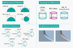
Image 1. Unique kernels of CAD packages can contribute to model variance during translation.
For instance, a cylinder shape or draft angle as represented in a CAD system that originated its own mathematical kernel will vary slightly from one vendor to another. So will the 3D annotations and attributes, defined as Product Manufacturing Information (PMI) that guide production machines in forming, cutting or growing parts. Those variations impact both OEMs and supply chains. When two separate software systems trade data between partners, say PTC Creo to Siemens NX, the geometry differences must fall within tolerance. Mating surfaces must meet manufacturing tolerances in order to join composite panels. Geometries need to be identical in order for FEA to accurately determine stresses around threaded holes and part interfaces. Innovation lives in the tool sets, but agreement between mixed tools is as important as geometry creation itself.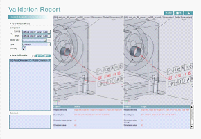
Image 2. Shown above is Elysium’s 3D PDF validation report detecting an engineering change in which a hole diameter has been modified from 40 mm to 52 mm. Associative geometry is highlighted for easy interpretation.
What people think
Many engineering professionals in aerospace understand and embrace digital automation for its design and manufacturing benefits, and its capacity for management oversight. Engineers in general, however, naturally wish to design, test and produce. They are less interested in coding nuances within CAD/CAM/CAE that are not visible in their programs and that manifest problems in hard to determine areas. Nonetheless, the labor involved in manual fixes, and the potential for poor yields and missed deadlines, are increasingly driving companies to take note of inherent shortcomings in system interoperability. There is also a growing awareness that standard data translation through direct solvers and reengineering does not always provide enough accuracy for sensitive, high-spec programs.
In seeking to take advantage of interconnected manufacturing work cells and integrated analyses, OEMs know that the hand-off of data to specialized suppliers and internal “consumers” must be solid for native-to-native programs as well as disparate software systems. Those outside specialties include multiphysics such as Computational Fluid Dynamics (CFD), or margin-of-safety and manufacturability analysis of composites. The results from all of these programs must reside in a verified Master Model, be that Dassault Systèmes CATIA, PTC Creo, Siemens NX or another major system. In this way data can migrate to design, manufacturing and management via a translated 3D PDF, HTML, or other “digital twin” and remain as accurate in ten-plus years when needed for other, new product authoring and test approaches.
Data interoperability, repair, translation and validation
Software quality tools for CAD should be thought of in the same way that the aerospace industry has come to accept hardware-based tools and methods for ensuring Six-Sigma practices on the factory floor. Interoperability software takes exchanged data between CAD systems and applies a menu of pre-chosen quality standards and checks, offering feedback, repairs and verification to the original digital model. The software also verifies that the data is not just valid mathematically for model exchange but also for manufacturability. There are specific checks increasingly available to ensure that the data is correct for mold making, machining, sheet-metal stamping, and industrial 3D-printing. Such capabilities get to the core business value of interoperability: saving time and preemptively fixing flawed models before they go downstream to manufacturing where scheduling, labor and material expense are affected.
Advanced interoperability and translation programs for accomplishing MBD/E provide:
- Interactive geometry verification and healing for multi-CAD data exchange, geometry simplification for CAE, plus tools for Rapid Prototyping and Reverse Engineering
- Feature-based design conversion for remastering CAD and legacy CAD files and process control
- Secure, integrated solutions for ensuring data translation and exchange quality, managing design data and workflows, and integrating the supply chain
- Robust validations and clear reporting of differences between geometry, attributes, 3D annotations (PMI), and more, for any derivative formats, engineering changes, and CAD upgrades versus their respective master models.
The end result of model repair and validation is connectivity, speed and the elimination of an “as manufactured” production model that does not match its 2D and 3D digital design versions.
Key to aerospace and defense interoperability is leveraging a neutral format that respects and accommodates all necessary formats for comparing the prime authoring data (geometry and complete PMI) with data returning from suppliers and internal parties. There is no room for approximations in these CAD exchanges. The neutral format engine that enables clean, accurate data between systems must have a robust underlining science for reconciling differences and then storing approved “flavored” data configured specifically around the final targeted format, whether it be another CAD system or standard neutral format, such as STEP.
The best conversion and validation techniques use the Application Programming Interface (API) from each CAD vendor. APIs are the middleman between the unique math kernels and outside requests for how to interpret and use modeling content. As such, they hold the source information that a well-designed neutral format engine can reconcile with incoming modeling-and-attribute data and prepare for translation to other stakeholders.
Image 3. The Elysium Neutral File (ENF) uses the original Application Programming Interface (API) from each CAD system to ensure accuracy in all types of processing, whether it be translation (import and export), quality checking, healing, validation, and even geometry simplification.
The neutral format program for validation itself is a work of innovation. The best ones accommodate all major CAD systems and neutral/standard formats, representing nearly any authoring system data without “modifying” the data itself. These advanced approaches do not live by their own set of rules to define geometry or topology; rather, they recognize all original sources. They are also able to identify issues in geometry that may or may not be conducive to a specific CAD kernel. For example, certain geometry may be represented in Siemens NX without issues, but the same model’s geometry or topology may cause problems in Dassault Systèmes CATIA V5 because of the variance in kernels. Advanced NF software engines such as Elysium’s understand each data set “as is,” according to the actual CAD API, and cannot only translate smoothly but also identify errors and heal accordingly to ensure seamless interoperability.
Examples of aerospace and defense model validation
API Validation: An aerospace Tier 1 supplier needed to validate all their 3D CAD translations and derivatives that go to downstream processes. They first evaluated a method that did not utilize the APIs of their various CAD systems. When they later benchmarked examples of the same data extracted through an API versus without, it became very clear that utilizing APIs was the most efficient and only reliable method for achieving accuracy. A direct read, or reverse-engineered approach to extracting data, poses risks and can introduce errors that may lead to false detections in the validation. Simply filtering these errors out of the results is highly undesirable and contradicts the objectives of reliable automation that industries are after, particularly in preparation for the MBE or similar digitalization initiatives.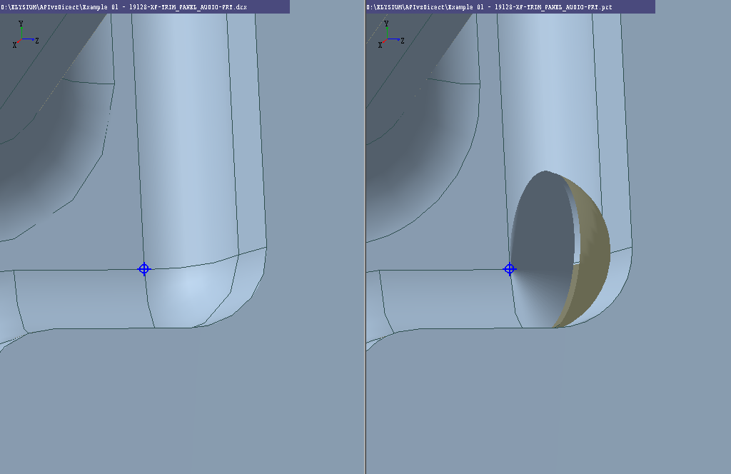
Image 4. This screenshot shows trim around an electronic component in a standard dashboard: Trimming edge of corner fillet is not trimmed properly (right) and completes a circle with attached faces, affecting both geometry and topology so it is not conducive for passing downstream. This fidelity loss occurs when 3D data is extracted by a direct read, or a reverse-engineered approach. By extracting data with utilization of the actual CAD API (left), the data fidelity is maintained and geometry is precise.
2D and 3D automation: Many OEM and Tier 1 aerospace and defense contractors are migrating from 2D drawings to 3D models to better communicate engineering change notifications. Interpreting changes in 2D are done manually because the space available to describe the change is limited—a typical description needs to fit within a title block, for example. If the intent of the change is not clearly defined, the interpreter then risks missing a parameter and manufacturing the new product incorrectly, which in aerospace can easily lead to millions of dollars wasted. Perhaps multiple changes were recorded in the 3D model but only one was realized in the drawing! The need to automate and track information is a crucial part of achieving the value of MBE and applying knowledge to next generations of the product. Producing reams of paper documenting the intelligence behind these products is not only time-consuming and inefficient, but highly prone to error. If the change is actually in a 3D representation that is directly connected to the Master Model, changes are highlighted and reported. Viewing in 3D is far more universal than interpreting text, especially across the global enterprise.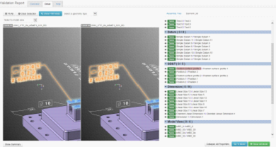
Image 5. An example of an Elysium HTML validation report comparing two CATIA models from different versions. The graphics area and Element List confirm that the GD&T are identical from version to version.
Feature accuracy and migration: Individual points within a CAD model represent specific processes, such as welds and fasteners. If the exact position of these coordinates is not validated when the CAD models are transferred to derivative formats, or upgraded to a newer version of the same CAD, then any changes can drastically affect lead time, and potentially affect the quality of the build, including FAA certification. One aerospace company is quite aggressive in its plans to reconcile its derivatives and upgraded versions. They process all certified data, which is approximately 500,000 models, when it is time to upgrade CAD systems. With each new change in hardware and software these models will be re-validated for accurate sustainment. The ideal state is to accept data regardless of its origin, enable deliverables in any required formats and move toward levels of automation that will provide higher quality, speed and efficiency.
Conclusion
Automation in CAD has been increasing steadily since the introduction of wireframe models. It has been accompanied by the corresponding automation of production and the deepening interface between design and manufacturing. With the advent of MBD/E, this trend will continue toward the realization of fully digital design-and-inspection loops and other expressions of Industry 4.0 and IoT. Data validation and interoperability are the deep waters that run under geometry creation, analysis, semantic PMI and visualization—ensuring that aerospace and defense platforms sustain quality and continuity during project rollouts that can last decades.